Hardware
Setting & Mode Configuration
Jumper Settings for RS-422 or RS-485
Inside the unit, there is a 10 x 2 (20 pin) header block which is jumpered to select the mode of operation. You will need to open up the plastics or metal covers, and set the jumper setting to RS-422 mode or RS-485 mode as per the requirements of your application. After the setting of jumpers and connecting power supply to the adapter, you then plug the adapter to USB port to start driver installation.
The RS-422 & RS-485 Mode Block Configuration Settings are listed as follows.
Example jumper block setting ( RS-422 mode )
RS-422 Mode Block Configuration
|
Jumper |
Function |
|
1-2 |
TxD
/ RxD Termination of 120 Ohm. This jumper
should be always populated for RS-422 mode. |
|
3-4 |
CTS
/ RTS Termination of 120 Ohm. This jumper
should be always populated for RS-422 mode. |
|
9-10 |
TxD
Driver Always ON. As RS-422 is full duplex point to point, the
transmitter should always be enabled. |
|
13-14 |
RxD
Driver Always ON. As RS-422 is full duplex point to point, the
receiver should always be enabled. |
|
17-18 |
Enable
CTS Handshaking. This
setting allows the data flow to be controlled using CTS/RTS handshaking if
required by the application. |
Note : all other positions = no jumper populated.
RS-485 Mode Block Configuration
|
Jumper |
Function |
|
1-2 |
TxD
/ RxD Termination of 120 Ohm. This jumper
should only be populated at each
end of the cable to meet RS-485
termination requirements. |
|
5-6 7-8 |
TxD
/ RxD Single pair (half duplex
for RS-485). Populate both these
jumpers. |
|
11-12 |
Enable
TxD Driver only when transmitting.
This is required by the RS-485 as multiple devices can transmit over
the same twisted pair. When a RS-485 is not transmitting, it��s transmitter
must be turned off to allow other devices to communicate over the same wire. |
|
13-14 (Echo) OR 15-16 (No
Echo) |
RxD
Always Enabled. In this RS-485 mode characters transmitted by the RS-485
device will also be received by the same device. These echoed characters are
usually stripped out by the application software. Transmit
Data Echo Suppression Mode. In this mode characters transmitted by the RS-485
device will NOT be received by the same device.
In this mode there is no need for the application software to strip out the
transmitted data from the received data as it is handled by
the hardware. |
|
19-20 |
CTS
Always Enabled. As there is no hardware handshaking in RS-485, CTS should be
permanently enabled to allow unrestricted flow of data. If handshaking is
required for RS-485 it can be done using X-On / X-Off handshaking protocol. |
Note : all
other positions = no jumper populated.
Sometimes,
when operating in RS-422 or RS-485, it is necessary to configure
120
Ohm termination of the data transmission lines. Generally this must be done
in
the cabling, since this depends on the installation of connections. Before
applying the option, check your cable specification for proper impedance
matching.
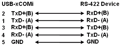
RS-422/485 Pin-outs & RS-422/485 Signal Wiring
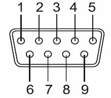
RS-422 Signal Pin-outs of DB-9 Male
|
Pin 1 |
TxD- (A) |
|
Pin 2 |
TxD+(B) |
|
Pin 3 |
RxD+(B) |
|
Pin 4 |
RxD-(A) |
|
Pin 5 |
GND |
|
Pin 6 |
RTS- (A) |
|
Pin 7 |
RTS+(B) |
|
Pin 8 |
CTS+(B) |
|
Pin 9 |
CTS- (A) |
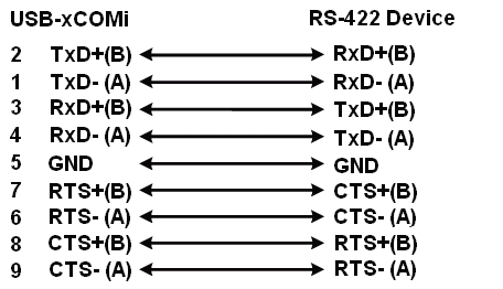
RS-422 Signal Wiring