Hardware
Setting & Mode Configuration
Outside the unit, there are two 3-pin DIP switches which are set to select the mode of operation. You will need to set the switch settings to RS-422 mode, or RS-485 mode, as per the requirements of your application. The RS-422 & RS-485 Mode Block Configuration Settings are listed as follows.
RS-422 & RS-485 Mode Block Configuration
SW1 (PORT1), SW2
(PORT2)
|
|
Operation Mode |
S1 |
S2 |
S3 |
|
RS-422
|
4 wire with handshaking |
ON |
ON |
ON |
|
RS-485
|
Full Duplex (4 wire) |
OFF |
ON |
ON |
|
Half Duplex (2 wire) with Echo |
OFF |
OFF |
ON |
|
|
Half Duplex (2 wire ) without Echo |
OFF |
OFF |
OFF |
Inside the unit, there are two 7x2 (14pin) header blocks which are jumpered to enable Tx,Rx, CTS 120 Ohm termination resistors and Rx, Tx 750 Ohm biasing resistor. You will need to open up the case and set the jumper setting for RS-422 mode or RS-485 mode as per the requirements of your application. Settings are listed as follows:
JP2 (PORT1), JP3 (PORT2) for
Termination and Biasing Option Configuration
|
Jumper |
Function |
|
1-2 |
Tx+/-
Termination of 120 Ohm. This
jumper should always be populated for RS485 Half-Duplex mode. |
|
3-4 |
This
jumper should be populated for pull-up |
|
5-6 |
Pull-down
This
jumper should be populated for pull-down |
|
7-8 |
Rx+/-
Termination of 120 Ohm. This
jumper should always be populated for RS-422 and RS485 Full-Duplex mode. |
|
9-10 |
Pull-up
Rx+ to VCC by 750 Ohm Bias
resistor. This
jumper should be populated for pull-up Rx+. |
|
11-12 |
Pull-down
Rx- to GND by 750 Ohm Bias resistor. This
jumper should be populated for pull-down Rx-. |
|
13-14 |
CTS
Termination of 120 Ohm. This
jumper should always be populated for RS-422 mode. |
Note
: Sometimes, when operating in RS-422 or RS-485, it is necessary to configure
termination
and biasing of the data transmission lines. Generally this must be done
in
the cabling, since this depends on the installation of connections. Before
applying
the
option, check your cable specification for proper impedance matching.
Biasing
of data lines must only occur at a single point anywhere in the cabling. USB‑2COMi-M
and
USB‑2COMi‑SI-M provide biasing for ease of installation. Please
be sure to
disable this inside the unit, if your cabling already provides biasing.
Termination must not be installed in the middle of the cable. It is only permitted at both ends. Since a computer controlled serial port is almost always at one end of the cable, termination is enabled by default.
RS-422/485
Pin-outs & Signal Wiring
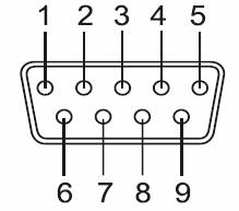
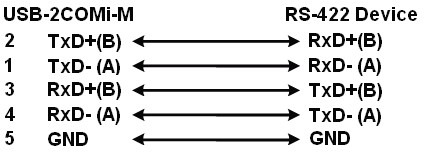
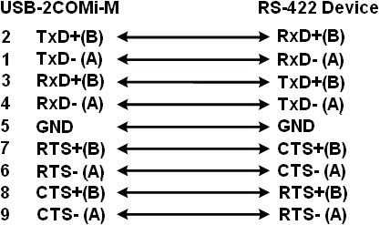
RS-422 Signal Pin-outs of DB-9 Male (CN2, CN3)
|
Pin 1 |
TxD- (A) |
|
Pin 2 |
TxD+(B) |
|
Pin 3 |
RxD+(B) |
|
Pin 4 |
RxD-(A) |
|
Pin 5 |
GND |
|
Pin 6 |
RTS- (A) |
|
Pin 7 |
RTS+(B) |
|
Pin 8 |
CTS+(B) |
|
Pin 9 |
CTS- (A) |
RS-422 Signal Pin-outs of Terminal Block (TB1, TB2)
|
Pin 1 |
TxD- (A) |
|
Pin 2 |
TxD+(B) |
|
Pin 3 |
RxD+(B) |
|
Pin 4 |
RxD-(A) |
|
Pin 5 |
GND |
RS-422 Signal Wiring